Semantic model
In the geometric relationships between entities blog post, we explained the types of geometric relationships that Digi3D.NET can analyze and introduced a set of commands that let you test these new relationships (and find errors, since there is bound to be a case we have not considered) and learn when the application returns a positive or negative result when analyzing geometric relationships between two entities. By themselves, however, those commands served only for learning or debugging. What we present to you today is the reason why this logic was added to the program, which is nothing more than the possibility of adding a Semantic Model, Data model, Cartography Quality Control Model, or whatever you want to call it, from now on I will call it Semantic Model. Thanks to this new feature, you will be able to do works such as M.G.C.P., B.T. A., Grafcan, Geomadrid, etc. with the certainty that what comes out of stereoplotting is well done, without any error, since Digi3D.NET is responsible for analyzing all the rules in real time, as you digitize. The possibilities are endless, as you will be able to see a little later. For this we have made the following changes to the program:
- We have added a new tab to the program Code table editor.
- We have added a new command to Digi3D.NET.
- We have added a new section in the configuration dialog of Digi3D.NET.
And then the things that are not seen:
- Many changes within the topology engine of Digi3D.NET.
- More changes within the topology engine of Digi3D.NET.
- And more changes ☺
Changes in the code tables editor.
We have added to the program Code Table Editor a new tab (you can see it in the image that heads this blog post) called Semantic Model that will allow us to add a series of rules that will define incompatibilities between entities. Rules are made up of the following components:
- The code of the entities to which the rule applies.
- The Type of entity to which the rule applies, which can be:
- Points.
- Open lines.
- Areas (polygons or closed lines).
- An error Message to display in case the rule is met (that is, in case any incompatibility is detected).
- One or more Conditions (which are basically relationships between entities).
- A boolean value (positive or negative) that indicates whether the rule is fulfilled if any of the above conditions result positive or negative.
- If we indicate here that the rule is met in case that some condition of positive, with that only one of the conditions of as positive result, it will be considered that the rule is met.
- If we indicate here that the rule is fulfilled in case that any condition of Bilinear interpolation, all conditions will be analyzed, and in case that all of them give as negative result, it will be considered that the rule is fulfilled.
Optionally, the following components can also be added to a rule:
- Name of the rule, such as Error 127.
- A URL to open a browser to a page explaining the detected problem.
For example, suppose we want to display the error message: Contour lines cannot end within an ocean area if the operator draws a contour line that enters within an ocean area. Let's assume that the contour line code is: Curva and that the ocean code is (surprisingly): Ocean. Well, we can add a rule that says:
- If the entity has the code: Curva
- And it is of type: LINE
- Display the error message: Contour lines cannot end within an ocean area
- In case of any of the following conditions:
- The line terminates inside the area
- The line terminates in the border of the area
- From as result: True
If the operator draws a contour line, in case the contour line code has active real-time semantic model analysis (I will explain it later), Digi3D.NET analyzes all the rules added in the semantic model and, in case it locates any rule in which the code is involved: Curva will check if the rule is fulfilled, if so, it will display a message box to the user indicating the error condition, which in this case will be the message Contour lines cannot end within an area of ocean.
Add a rule is very simple, we just have to press the button Add rule in the Semantic Model tab of the program Code table editor.
The Add semantic rule dialog box will appear that will allow us to enter a code or a tag (if you include a tag, all codes that have that tag will be considered), the type of entity to which the rule will be applied, the error message to display, the boolean that indicates if the rule is fulfilled if the conditions are positive or negative and the two optional title and URL fields as you can see below:
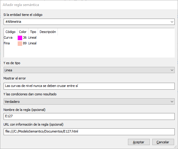 In this screenshot you can see this dialog box showing the data needed to add a semantic rule for all codes that have the tag Altimetría, in which also the optional fields Name (I have invented that that is the error 127) and URL have been filled. If you notice the URL I have put it so that it points to a local file. It would already be your responsibility to create there a file with that name (E127.html in this case) that explains to the user information regarding that particular error.
If you look at this dialog box, we are not entering the conditions, we have only created the rule. If we accept the dialog box, a rule without any conditions will be added to our list of rules...
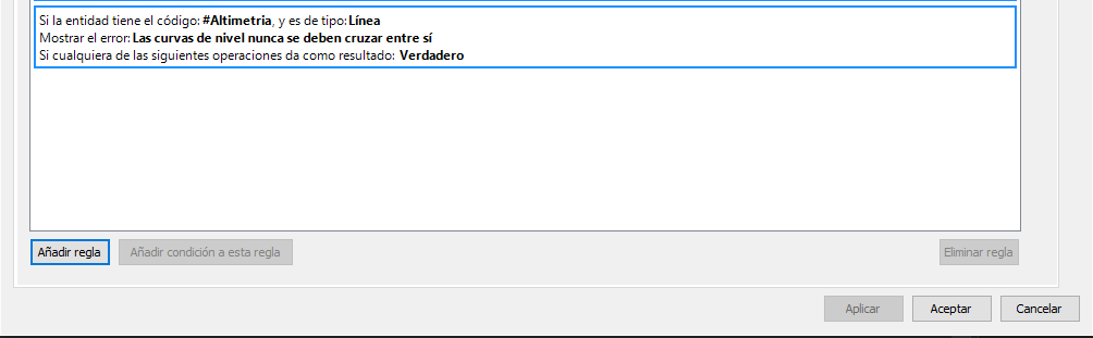 To add a condition, select the rule and press the Add condition to this rule button. The Add condition to semantic rule dialog box will appear.
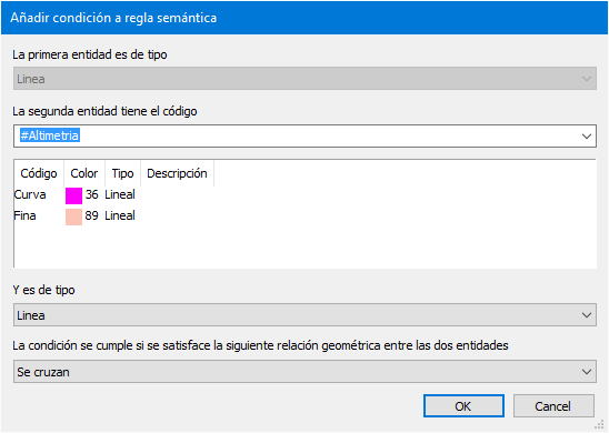 This dialog box will allow us to add a condition (which is nothing more than a geometric relationship between two entities) to the rule.
In a condition we indicate the following components:
- The code of the second entity.
- Type of the second entity.
- The geometric relationship between the two entities.
The list of possible geometric relationships obviously varies depending on the entity type of the first entity and the second entity. In the following table I show you the set possible relationships depending on the type of the first and second entities:
| First entity | Second entity | Possible relationships |
|---|---|---|
| Point | Point | * Disjointed. * Matched. |
| Point | Line | * Disjointed. * Match. * The point matches one end of the line. |
| Point | Area | * Disjointed. * Match. * The dot is inside the area. |
| Line | Line | * Disjointed. * Join. * Join at their ends. * The end of the first line joins the second. * Cross. * Overlap. * Equal. |
| Line | Area | * Disjointed. * The line ends at the edge of the area. * Join. * The line ends inside the area. * The line crosses the area. * Adjacent. * The line is completely inside the area. |
| Area | Area | * Disjointed. * Join. * Adjacent. * The first area is completely included within the second area. * The first area completely includes the second area. * The first area is included within the second area. * The first area includes the second area. * Overlap. * Equal. |
As you can see, there are no Area->Point, Area->Line, Line->Point relationships and there is no point in adding them, because the rules are executed whenever the code of the digitized entity is involved in the rule (whether its code matches the main code of the rule or that of any of the conditions that the rule has), so for example in the case of wanting to mark as errors contour line lines that end within an ocean area, creating the rule that defines that contour line lines cannot end in ocean areas is enough. This rule will be applied every time we digitize a contour line line but also every time we digitize an ocean area. Digi3D.NET will take care of doing things right automatically.
Finally, we have to indicate to Digi3D.NET if we want these rules to be parsed in real time, at the moment the user is digitizing an entity. We may not want to parse them in real time, but we want to parse them on demand (we will talk about this in the next blog post), so there has to be some way to indicate that the rule should not be applied in real time.
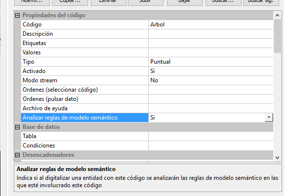
For this we have added an additional property to the Code properties of each of the codes that appear in the Codes tab of the Code Table Editor program
This property is called Analyze semantic model rules. If it is enabled, when we finish digitizing an entity, all the rules in which that entity is involved will be analyzed.
You can see that new property in the following screenshot:
One more command for Digi3D.NET
There has to be some way to turn this on and off, don’t you think? You might want to temporarily disable real-time scans, and turn them on a little later. For this we have added a command in Digi3D.NET named ANALIZAR_MODELO_SEMANTICO which is a boolean type variable that is activated by default and that if activated starts the semantic analysis of the entities whose codes have the semantic model active in real time.
A new configuration section in the configuration dialog of Digi3D.NET
And finally, we have added in the configuration dialog of Digi3D.NET a section called Semantic Model in which we can indicate parameters such as the preferred method of communication of messages (message box, balloon, speech synthesis, task window). You can see it in action in the video below: