What's new in absolute orientation calculation
[caption id="attachment_700" align="alignnone" width="625"]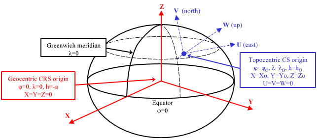 Graph showing the geocentric and topocentric systems[/caption]
The calculation of absolute orientations in Digi3D.NET can be performed in three different coordinate systems:
- On a local system.
- In a topocentric system.
- In a geocentric system.
The absolute orientation is a two-way mathematical transformation that transforms a coordinate A (or coordinate Terrain) into a coordinate B (or coordinate Model) by means of a Helmert of 7 parameters (it consists of applying a unique scale factor in the three axes, a rotation and a translation). When we make an absolute orientation in Digi3D.NET in a photogrammetric model, we consider A a coordinate of the ground control points and B a coordinate measured in the photogrammetric window. If the photogrammetric window has loaded a conical camera model to which we have just made a relative orientation, these coordinates will be of the type (X photo, Y photo, -focal) and if the window has loaded a satellite model for example these coordinates will be of the type (Latitude, Longitude, Altitude (ellipsoidal)).
This transformation is only a scaling, rotation and translation, so no coordinate system transformation is performed, which means that the coordinates A (or Terrain) measured must be in the same coordinate system as the coordinates B (or Model) measured when calculating the absolute orientation.
The problem is that sometimes the coordinate systems of the coordinates of the ground control points and that of the photogrammetric window on which we are measuring do not match.
[caption id="attachment_719" align="alignnone" width="450"]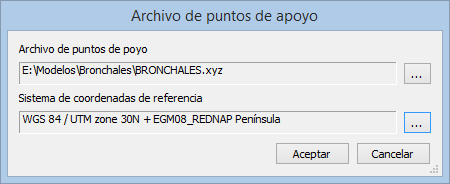 The new ground control points file selection dialog prompts the user for the reference coordinate system of the ground control points.
[/caption]
If we make an absolute orientation in a satellite image, the coordinates A (or Terrain) of the ground control point that we are measuring will be in the reference coordinate system that we indicate when loading the ground control points file, however the coordinates B (or Model) that we generate when digitize the point will be in the satellite image coordinate system, which are geographic coordinates in WGS 84.
Therefore Digi3D.NET has to locate a common reference coordinate system to perform the Helmert transformation of 7 parameters. This system we will call intermediate system.
Let's see the steps that follow Digi3D.NET to transform a coordinate Terrain to Model with a given absolute orientation:
Terrain -> Intermediate system -> Helmert of 7 parameters -> Model
and vice versa:
Model -> Intermediate system -> Helmert of 7 parameters -> Terrain
As you can see the Helmert of 7 parameters is always performed in the intermediate system.
Intermediate System Selection
Let's now look at the criteria that follows Digi3D.NET to decide and create the intermediate system. This decision is made based on the coordinate systems of the photogrammetric window and the ground control points:
| Coordinate system of the photogrammetric window | Coordinate system of ground control points | Resulting intermediate system |
|---|---|---|
| Unknown | Unknown | The intermediate system is an unknown system. The Terrain<->Intermediate System and Intermediate System<->Model operations do not perform any transformation. When making an absolute orientation under these conditions, the earth is assumed to be flat and therefore calculations are not affected by projection, curvature or scale factor. This is the case where absolute orientations were calculated with the versions Digi3D 2000, Digi3D 2002, Digi3D 2005 and Digi3D 2007 (in this case, if selected as a rectangular coordinate system when measuring absolute orientation). |
| Unknown | Known coordinate system, such as WGS 84 or ETRS89 / UTM Zone 30N | This is the typical case of the conical camera model in which we have made a relative orientation (therefore the model coordinates in the photocenter of the left camera will be (0,0,-focal) and in which we make an absolute orientation with ground control points in a certain reference coordinate system. In this case Digi3D.NET creates a coordinate system topocentric, which is a Cartesian system 3D that has three perpendicular axes (L, V and W) whose origin is tangent to the earth at a certain point. The L axis is oriented with the east, the V with the north and the W grows according to the rule of the right hand. It is the blue color system in the image that appears at the beginning of this post. It is considered as the origin of the topocentric system the geocentric coordinates of the first point measured (Digi3D.NET transforms the coordinates of the ground control point of the first point measured to geocentric to be able to perform this operation). |
| Known coordinate system, such as WGS 84 or ETRS89 / UTM Zone 30N | Unknown | This situation occurs for example if in the photogrammetric window we have a satellite image and we want to make an orientation with local or unknown ground control points. In this case Digi3D.NET creates a coordinate system topocentric, which is a Cartesian system 3D that has three perpendicular axes (L, V and W) whose origin is tangent to the earth at a certain point. The L axis is oriented with the east, the V with the north and the W grows according to the rule of the right hand. It is the blue system in the image that appears at the beginning of this post. It is considered as the origin of the topocentric system the geocentric coordinates of the first point measured (Digi3D.NET transforms the coordinates of the measured point in the photogrammetric window to geocentric to be able to perform this operation). |
| Known coordinate system, such as WGS 84 or ETRS89 / UTM Zone 30N | Known coordinate system, such as WGS 84 or ETRS89 / UTM Zone 30N | In this case you might think that no transformation is necessary, but it is, because the systems might not be orthogonal. If in both windows we have WGS 84 for example, the units measured are angles and not coordinates. We cannot make an absolute orientation to adjust angles. Therefore the absolute orientation is calculated in geocentric coordinates. It is the red system in the image that appears before this table. To make the calculation, the coordinates of the ground control points are transformed into geocentric coordinates (therefore the projection is taken into account if the coordinate system of the ground control points is projected, such as ETRS89 / UTM Zone 30N, the curvature of the earth and the scale factor. The same is done for the coordinates measured in the photogrammetric window and finally the Helmert of 7 parameters in the geocentric system. This is the ideal system, because it takes into account the different projections both of the ground control points on the one hand and the system of the photogrammetric window on the other. |
How do we select the reference coordinate system in the photogrammetric window?
Read the entry Changes in sensor reference coordinate systems.
Where and when are these transformations taken into account?
Suppose the drawing window is displaying vectors in a coordinate system A, and the photogrammetric window is assigned a coordinate system B. If there is no absolute orientation in between, Digi3D.NET when projecting vectors in the photogrammetric window, you just have to transform the coordinates of the vectors from the coordinate system A to the coordinate system B. When the user moves the photogrammetric window (using the mouse or topomouse or handwheels), it sends the coordinates to the drawing window by transforming them from the system B to the system A. If there is an absolute orientation in between, the absolute orientation has its own reference coordinate system, which could be C, so that the transformation Drawing window -> Photogrammetric window follows the following steps: System A -> System C -> System B. And vice versa, when the photogrammetric window has to inform the drawing window of a coordinate, it transforms the coordinate following the following steps: System B -> System C -> System A.
How can I know the coordinate system that has assigned the absolute orientation?
You can use the photogrammetric window/View Info menu option, which will display in the result pane the reference coordinate system assigned to the orientation and the photogrammetric window.