Changes to the camera system
Due to the incorporation of the distortion correction model in cameras calibrated with Pix4D, PhotoScan and with OpenCV, we have made a number of changes to the camera concept in Digi3D.NET.
The changes made are internal and we have maintained backward compatibility, so that the cameras created today will continue to behave in the same way.
A digital stereoplotter such as Digi3D.NET basically shows images by centering a certain pixel of these images in the center of the photogrammetric window. When you move the input device (handwheels, topomouse, mouse, etc.) values are increased or decreased to the Terrain Coordinates and the corresponding sensor is responsible for transforming these Terrain Coordinates to Pixel Coordinates in which each image displayed in the photogrammetric window will have to be centered, so that the responsibility of transforming from Terrain Coordinates to Pixel Coordinates falls on the sensors (which in Digi3D.NET are implemented as extensions).
Each sensor (ADS, Satellite, Conical Cameras, etc.) goes through a series of calculations (specific to the sensor's mathematical model) to fulfill that mission: Transform from Terrain Coordinates to Pixel Coordinates.
The changes we have introduced here apply to the Conic Sensor (the pinhole camera), the rest of the sensors have not been touched.
Let's see how this sensor behaved until today to transform from Terrain coordinates to Pixel coordinates:
 The Exterior Orientation took Ground Coordinates (Xt, Yt, Zt) as input parameters and provided Photo Coordinates (Xfo, Yfo) as output. To do this, the Exterior Orientation had to know which camera we were working with, because the camera's Focal length is involved in calculating Photo Coordinates. As you will see later, we have changed this: Exterior Orientation is now independent of the camera being used and therefore has no knowledge of a camera's existence.
The mission of the Camera was to transform the Photo Coordinates into Fiducial Coordinates (Xfi, Yfi) correcting lens distortions if necessary.
The mission of Internal orientation was to transform from Fiducial Coordinates to Pixel Coordinates (Xp, Yp).
Distortion corrections were made in the passage from Photo Coordinates to Fiducial Coordinates only. Also, you can see that we had to have either or an internal orientation.
It turns out that distortions in Pix4D, PhotoScan and calibrations obtained by any program that uses the OpenCV machine vision library do not correct distortions in the photo system, but are corrected in the Projected Camera System. In addition, no internal orientation is necessary because the mathematical model for these cameras transforms directly to pixel coordinates.
Let's see how the conical sensor of Digi3D.NET behaves to transform from Terrain Coordinates to Pixel Coordinates after making the changes we present today:
 Outer orientation now does not return Photo Coordinates (Xfo, Yfo), but instead returns Coordinates in the Camera System (Xcam, Ycam, Zcam). Camera's mission now is to convert those Coordinates in the Camera System to Pixel Coordinates (Xp, Yp).
Let us now study how to transform the camera from Coordinates in the Camera System to Pixel Coordinates:
 The first thing we do is convert from Coordinates in the Camera System to Projected Coordinates in the Camera System (by dividing both the component X and the Y by the Z).
Then we transform from Projected Coordinates in the Camera System a Photo coordinates. The implementations of Pix4D PhotoScan y OpenCV correct the distortions in this step. In this phase, the Focal length (or rather, the focal lengths of the camera, because now two focal lengths can be entered if necessary (if the camera is calibrated in pixels and the sensor is cheap, it is possible that the width of the pixel does not match the height of the pixel, therefore we get two different focal lengths).
We continue transforming from Photo to Fiducial. It is in this phase where Digi3D.NET calculated the distortions. Pix4D, PhotoScan and OpenCV cameras basically add up the coordinates of the main point here.
And finally the Fiducial Coordinates are transformed into Pixel Coordinates. If the camera is analog, this is where the internal orientation is taken into account, and if not, then basically multiply the Fiducial Coordinates by the size of the Pixel and add the coordinate of the Pixel center of the image (which is the 0,0 in the fiducial system).
Digi3D.NET now natively loads Pix4D files (shortly PhotoScan and OpenCV if there is a standardized format for OpenCV, I have to study it), so you don't have to do anything else but load the corresponding camera file and Digi3D.NET takes care of everything, as you can see in the blog entry Loading natively Pix4D camera calibration files, however, we have also modified the camera files of Digi3D.NET so that you can create a camera file in Digi3D.NET format and that it works the same as Pix4D for example.
Let’s see how these parameters have turned out:
| Variable | Value | Default value | Description |
|---|---|---|---|
| Focal length | * If the focal has the same dimensions in X and in Y, a single value with the focal value. * If the focal has different dimensions in X and in Y, two values: one for the focal in X and another for the focal in Y. | N/A | The units of this value define the units of the other values in the camera file, which indicates that if we set this value in millimeters, the units of the other variables must be in millimeters. You can enter a value here in any unit, provided that the other variables use the same unit. |
| CorrectionType | * * * * * * * * * * | FotoAFiducial | Indicates at which step the camera distortion correction will be performed; by default this value is PhotoCamera for backward compatibility. |
| TangentialDistortionType | * No. If you do not want to apply tangential distortion. * Brown. If you want to apply the following formula:∆x = P1*(r2 + 2*x2)+2*P2*x*y**∆y = 2*P1*x*y + P2* (r2 + 2*y2) * OpenCV. If you want to apply the following formula:*∆x = 2*P1*x*y + P2*(r2 + 2*x2)*∆y = 2*P2*x*y + P1*(r2 + 2*y2) | * If this variable and the P1 and P2 variables are not specified, the default value is No. * If this variable is not specified and values for the P1 and P2 variables appear in the camera file, for backward compatibility the default value is Brown. | These distortions are caused by a poor alignment between the lens and the sensor, which can lead to distortions in the image. |
| Disortogonality Type | * No. If you do not want to apply desortogonality. * Fraser. If you want to apply desortogonality on the axis of the X by the formula: ∆x = B1*x + B2*Y | * If * this variable and the variables B1 and B2 are not specified, the default value is No. * If this variable is not specified but the variables B1 and B2 are specified, the default value is Fraser | It indicates the type of desortogonality (due to poor manufacturing of the CCD sensor in which the pixels may not have the same width as height or the pixel matrix is not perfectly aligned. |
I show you below the source code of the function that calculates the correction by distortion so that it is clear how distortions are calculated in Digi3D.NET (it is programmed in C++, but even if you do not understand programming I think you make a minimum effort to understand it you will see clear):
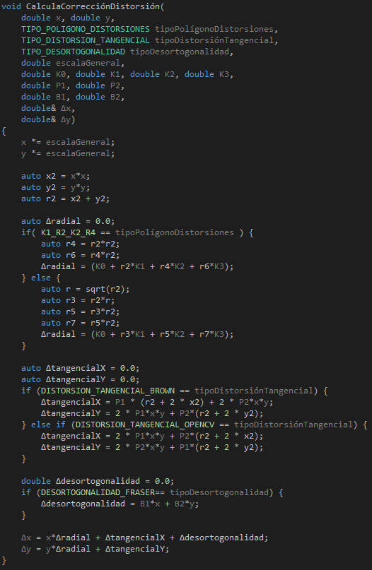 This way you can see how all the parameters of the camera file come into play.
Let's now see a practical case: Let's create a camera file in format Digi3D.NET that simulates the following Pix4D camera file:
Pix4D camera calibration file 0
#Focal Length mm assuming a sensor width of 23.64864599999999938973x15.76576400000000077739mm
F 25.21219253120580461314
#Principal Point mm
Px 11.78574296804639587322
Py 7.57715224585386515344
#Symmetrical Lens Distortion Coeffs
K1 0.00086121816472929343
K2 0.02791840536682562574
K3 -0.03806069473095977096
#Tangential Lens Distortion Coeffs
T1 -0.00621590311996760014
T2 -0.00051873958437360630
You can check that the sensor size in millimeters is shown (as a comment), but the pixel size and the size of the images are not shown anywhere. If you look at the calibration file it is indicated that the width of the sensor is greater than the height of the sensor, which means that the camera has been calibrated horizontally and the photos obtained with this camera should always go horizontally (disable the automatic rotation option), and so they would have to be loaded in Digi3D.NET. This particular camera creates images of 6000x4000 pixels, so the horizontal and vertical pixel size can be easily deduced by dividing the sensor width by the number of horizontal pixels on one side and the sensor height by the number of vertical pixels of the image giving the following results 23.648646 / 6000 = 0.003941441 15.765764 / 4000 = 0.003941441 Thus the pixel size in horizontal is the same as in vertical.Let's start creating our camera file:
[Camara]
TamanoPixel=0.003941441
The focal is clearly indicated that it is in millimeters as well, so we copy it as it is
[Camara]
TamanoPixel=0.003941441
Focal=25.21219253120580461314
We continue with the main point. The main point in Pix4D is given with respect to the upper left corner of the image, and not with respect to the fiducial center as we are used to, so we have to do a simple subtraction (coordinates that appear in the Pix4D file minus coordinates of the camera's fiducial center) to transform that main point to a main point with respect to the fiducial center which is as required by Digi3D.NET. The X and Y axes grow differently, so you will see that in the Y the operation is done reversely.
PuntoPrincipalXConRecpectoAlCentroFiducial = PuntoPrincipalXConRecpectoEsquinaSuperiorIzquierda - CentroFiducialX

PuntoPrincipalYConRecpectoAlCentroFiducial = CentroFiducialY - PuntoPrincipalYConRecpectoEsquinaSuperiorIzquierdaY
And the trust center is very simple: either divide by two the width and height of the sensor on one side, or divide by two the size of the image (the result will give us in pixels obviously) and multiply the value by the pixel size calculated above. I will use a formula for the X and another for the Y, so you have the two:
CentroFiducialX = 23.64864599999999938973 / 2 = 11.824323
CentroFiducialY = 4000 / 2 * 0.003941441 = 7.882882
Perfect, now to subtract and we have the coordinates of the main point with respect to the fiducial center:
PuntoPrincipalXConRecpectoAlCentroFiducial  = 11.78574296804639587322 - 11.824323 = -0.038580032
PuntoPrincipalYConRecpectoAlCentroFiducial  = 7.882882 - 7.57715224585386515344 = 0.3057297541462
Let's continue with our camera file:
[Camara]
TamanoPixel=0.003941441
Focal=25.21219253120580461314
PuntoPrincipal=-0.038580032 0.3057297541462
If we study the formulas used by Pix4D we will check that it performs the correction of distortion in the passage of Projected Camera Coordinates to Focal Coordinates, and that in addition the polynomial used for radial distortions is K1_R2_K2_R4, in addition it is used as tangential distortion type the OpenCV method and that it does not take into account the desortogonality, so that the camera file remains as follows:
[Camara]
TamanoPixel=0.003941441
Focal=25.21219253120580461314
PuntoPrincipal=-0.038580032 0.3057297541462
TipoCorreccion=CamaraAFoto
Pol=K1_R2_K2_R4
TipoDistorsionTangencial=OpenCV
TipoDesortogonalidad=No
K1=0.00086121816472929343
K2=0.02791840536682562574
K3=-0.03806069473095977096
P1=-0.00621590311996760014
P2=-0.00051873958437360630
And below you have a video in which it is demonstrated that with this camera file the results are identical as with the native camera of Pix4D.